


New features introduced with release
X9
Updates:
- November 2025: released the new version X9: download list of new features introduced >
CAD Environment
- New command "Path > Convert 2D line into 3D line":
This command allows you to create a 3D line from a 2D line in the drawing.
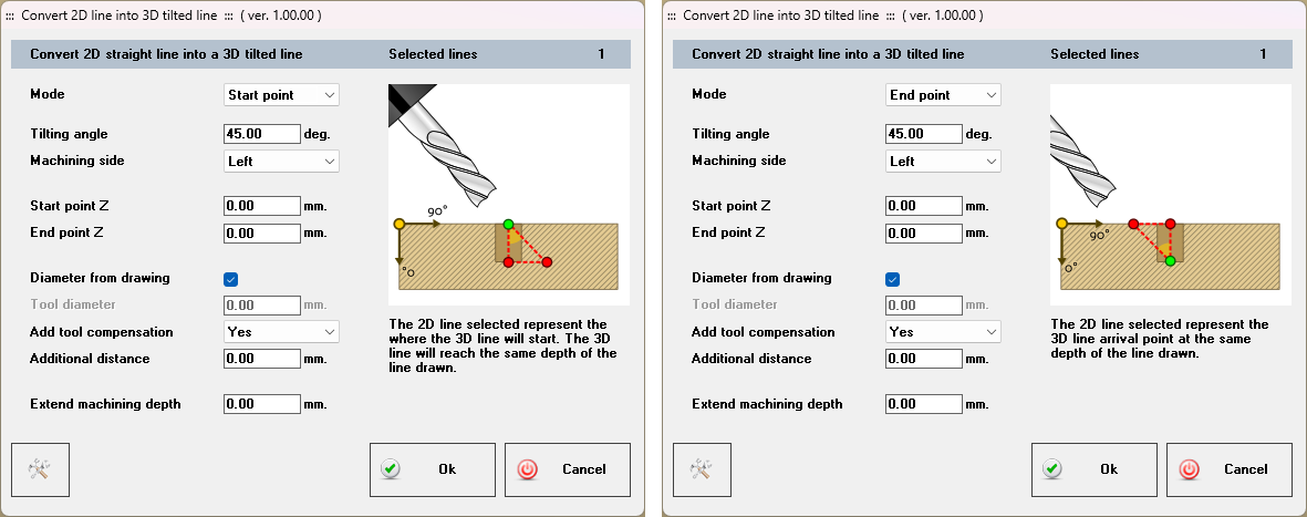
Two working modes are available:
1. "Start point":
The surface of the panel is used as the reference point for the 3D line.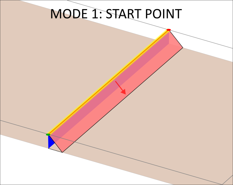
2. "End point":
The point on the line drawn at the specified depth is used as the reference point for the 3D line.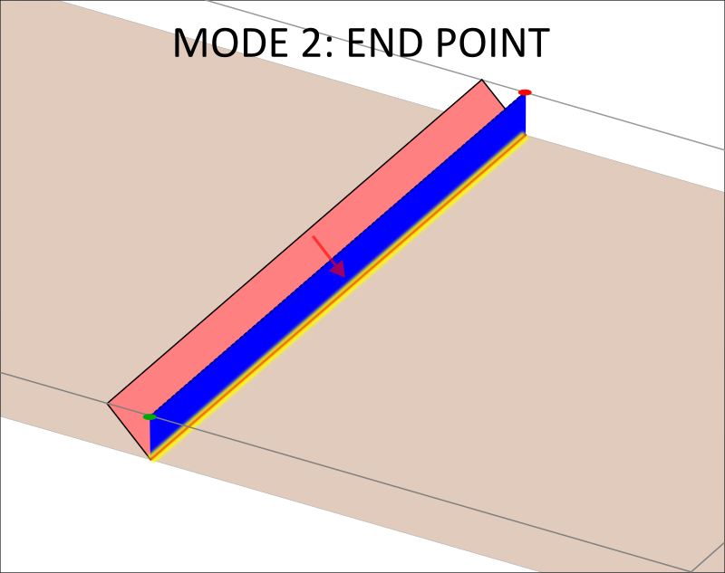
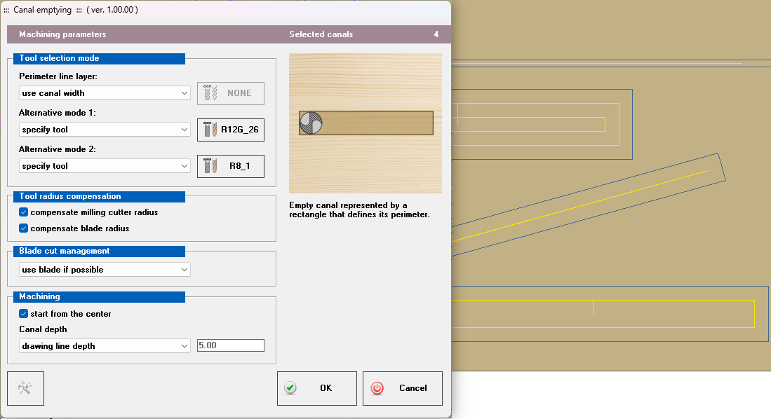
- New command "Tools > Empty canals":
Creation of canals starting from the rectangle that represents their perimeter.
- New command "Layer > Pick layer":
Allows the selection of an entity in the drawing and activation of the layer to which it belongs.

CAM Environment
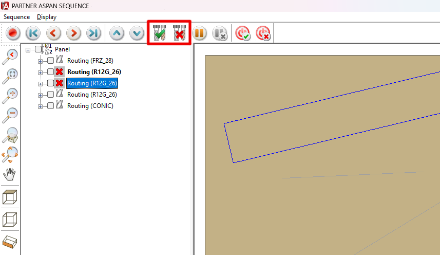
- Sequence: New commands "Enable / Disable Machining":
The commands allow you to quickly enable or disable one or more selected machining operations in the sequence tree. Disabled machining operations will not be included in the generated machine program.
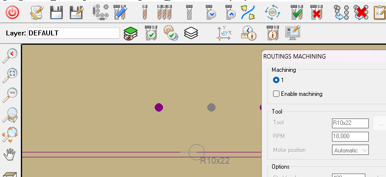
- Disabled machining operations are now indicated in CAM to allow for easier and more immediate identification.
- New command "Layer > Pick layer":
Also available in the CAM environment, it allows the selection of an entity in the drawing and the activation of the layer to which it belongs.

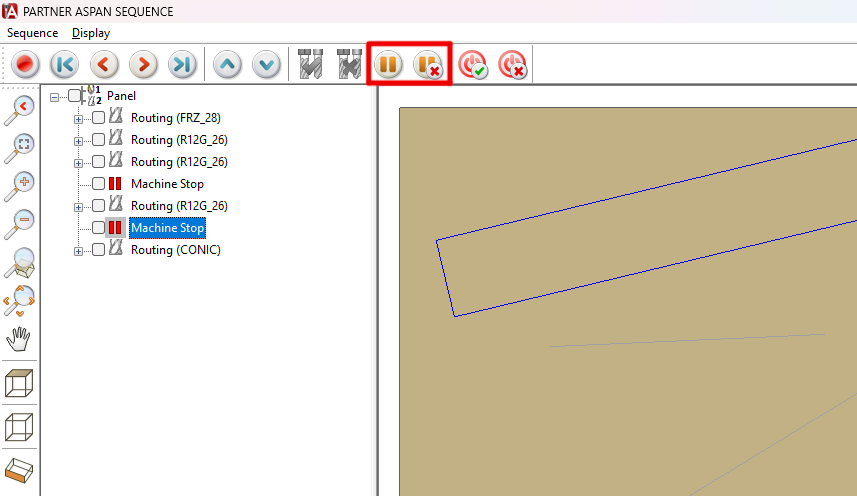
- Sequence: New commands "Insert / Remove Program Stop":
(available only for configurations with a processor that supports the operation)
The commands allow you to insert or remove a program stop operation from the sequence.
The operation will be inserted immediately after the selected machining operation in the machining tree. Stop operations can be moved in the same way as normal machining operations using drag & drop or the dedicated keys.
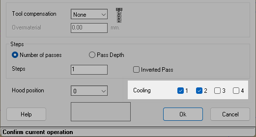
- Multiple refrigerant option selection:
(feature available only for processors that support its use)
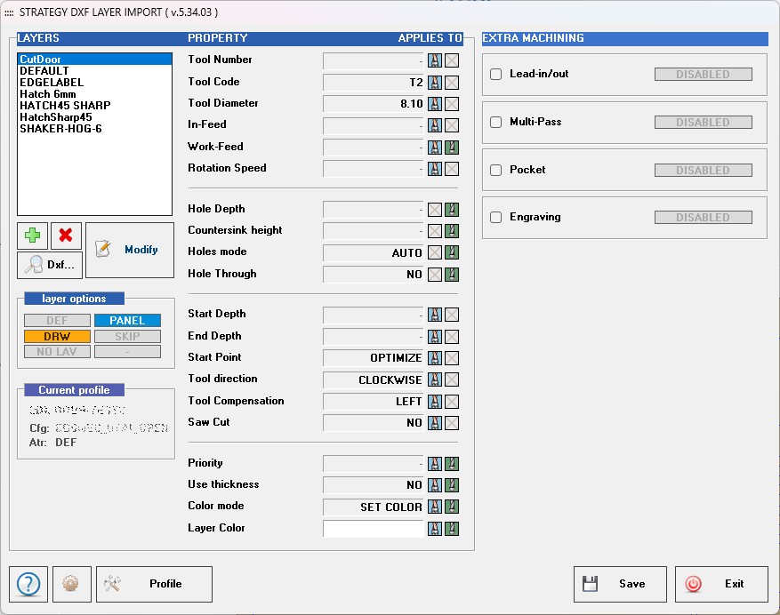
DXF import processor: Strategy_layer_import
- Optimized interface for improved readability.
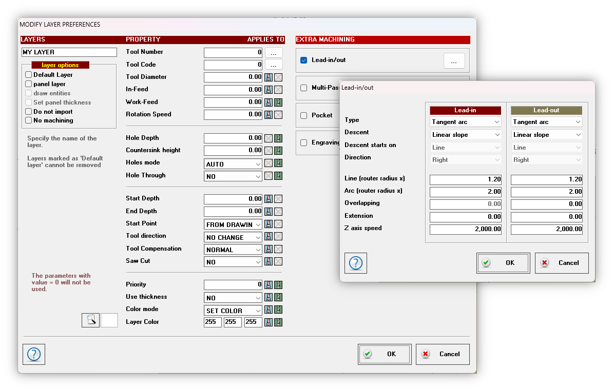
- Lead-in/out paths management:
It is now possible to automatically assign an entry and exit section to imported paths, configurable in terms of type (tangent line, perpendicular line, tangent arc, line + tangent arc, incision) and parameters (length, overlap, extension, etc.).
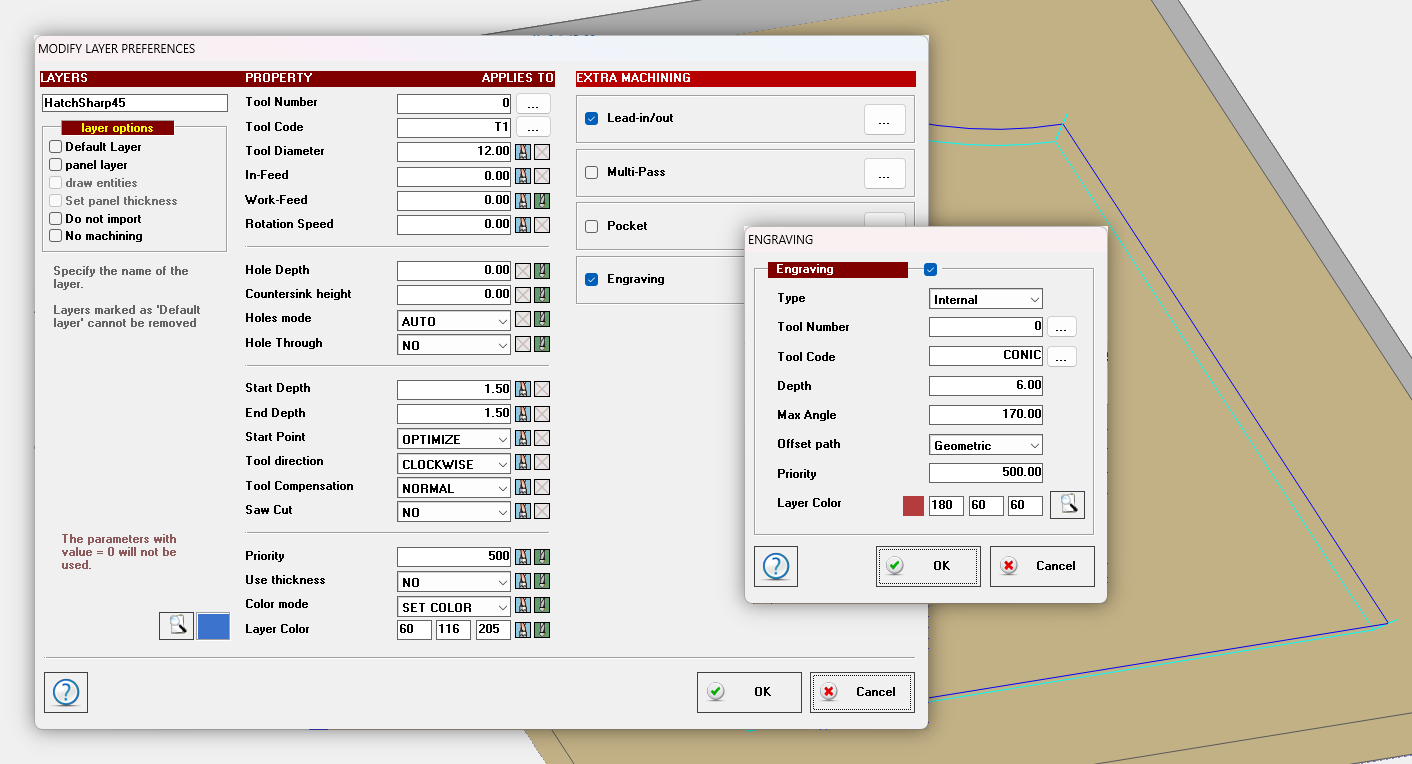
- Automatic creation of sharp edge cleaning paths.
Nesting Optional Module
- It is now possible to add to the labels the layout image with the position of the piece highlighted.
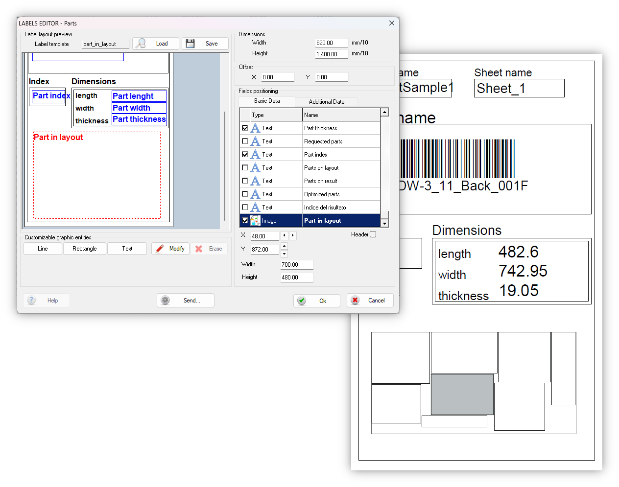
- New option "Keep tool correction for cutting paths" (Free-Form):
By enabling this option with the command “Process > Processing options” when importing free forms, the tool compensation position defined in the drawing will always be enforced.
Macro
- New commands "~SetLeadIn" e "~SetLeadOut":
Syntax
~SetLeadIn(<idx>, <type>, <slope>, <slope_start>, <side>, <multiplier_line>, <multiplier_arc>, <extension>, <feed>)
~SetLeadOut(<idx>, <type>, <slope>, <slope_start>, <side>, <multiplier_line>, <multiplier_arc>, <extension>, <feed>, <overlap>)
A tool must be assigned to the path before applying input or output with the commands indicated.
<idx>Shape idx <type>Lead-in/out type:
0 – none
1 – tangent line
2 – perpendicular line
3 – tangent arc
4 – line + tangent arc
5 - incision<slope>Descent type:
0 – vertical
1 – linear slope<slope_start>Descent starts on:
0 – line
1 – arc
(used only by line + tangent ark lead type)<side>Application side:
0 – right
1 – leftLenghts configuration <multiplier_line>Router radius multiplier applied on linear paths <multiplier_arc>Router radius multiplier applied on arc paths <extension>Extra distance in mm. <feed>Z axis speed (mm/min) <overlap>Overlap distance in mm. (only for lead-out) - New command "~CreateImg":
Create image of the current panel in the given path.
Syntax
~CreateImg(<path>, <size_x>, <size_y>, <face>)
<path>Full path and name of the image to create.
e.g. C:\ATS\PARTNER-ASPAN\Drw\MyPanel.jpg
Image extensions supported are bmp, png, jpg.<size_x>Image width in pixels.
Set the value to 0 calculate automatically the width in proportion with the height specified (in this case height value cannot be 0).<size_y>Image height in pixels.
Set the value to 0 calculate automatically the height in proportion with the width specified (in this case width value cannot be 0).<face>Panel face to be exported as image:
1 .. 6 – face number
0 – exploded view
Other improvements
- ASC/ASP: Do not merge lines belonging to different layers.
New default "AscAsp.JoinEntOnDiffLayers". If set to 1, ASC/ASP autojoin skips adjacent routing operations that belong to different layers. - Added support for new numeric controls.